ET3D – Electrothermal 3D
Introduction
Electrothermal 3D, ET3D, performs a thermal transient analysis on a heated, multilayered, structure in three dimensions. Consistent with general aerospace practice, these dimensions are referred to as ‘chordwise’ (front to the back of an aircraft wing or helicopter rotor blade), ‘layer’ (in the direction into and out (thickness direction) of the structure), and ‘spanwise’ (along the span of the wing or rotor), representing the ‘x’, ‘y’ and ‘z’ directions respectively.
Technical
The code may be run in 1D, 2D or 3D modes. It is envisaged that the code will be used mostly for 2D analysis (chordwise and thickness directions), with less frequent use applied to the analysis of 1D (thickness direction) and 3D (including the spanwise component) problems. This is driven by the limited usefulness of a relatively fast 1D analysis, and the large computational expense (long computer run times) of most 3D structures, even of small extent of, say, only a few centimetres.

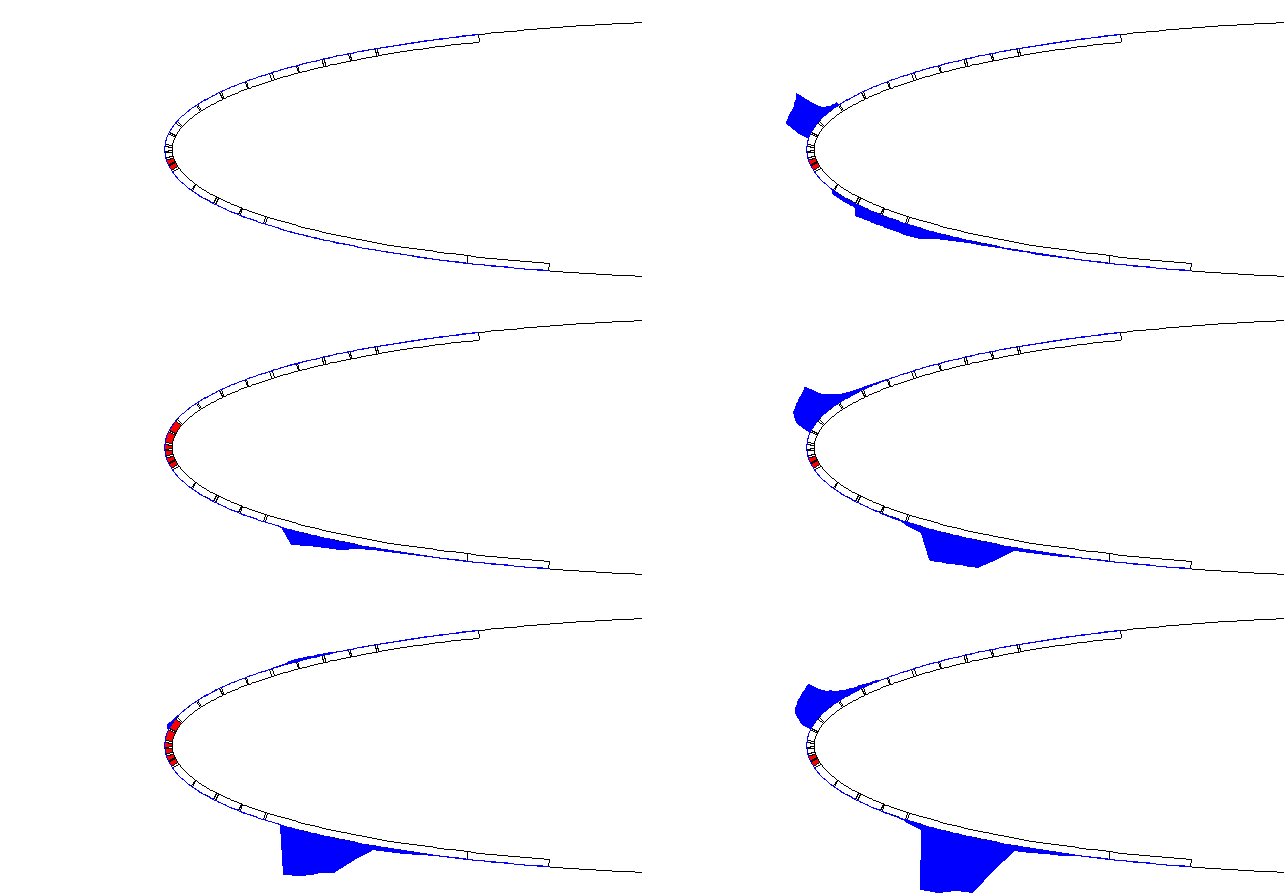
Example ice growth simulation
Note: Structure and ice thickness increased for visualisation purposes

Example structural temperature response
Note: Ice thickness multiplied by 20 for visualisation purposes
The code uses an explicit finite difference (FD) method to evaluate the new temperature of a number of control volumes (‘nodes’) after a small time step, typically 0.001 seconds. A Cartesian coordinate system is employed. The energy balance, control volume, approach sums the contribution of heat flow from the six directions (front, rear, top, bottom, left and right) and the net heat flow (positive or negative) is used to change the temperature (or the icing freezing fraction if the node is on the outer breeze surface) of the control volume either up or down. In an explicit FD scheme the equations are deterministic and all values and properties are evaluated at the ‘old’, current, timestep. Application of the equations gives the temperature after one time step, and the process is repeated until the required time period of analysis (usually several tens of seconds or many minutes, requiring many thousands of time steps to be calculated). A disadvantage of explicit schemes is that they are not conditionally stable, and this means that there are restrictions on the choice of nodal spacing and time step. The code will notify the user if the ‘stability criteria’ are not met, and report an acceptable value for time step. The nodal spacing (number of nodes assumed in each layer, or zone) and/or time step must then be changed before the program will conduct the transient analysis. An implicit FD scheme is favoured by many other agencies as it is unconditionally stable, and so any size of time step could be used and the program will return results. The solution of the equations is more complex at each time step as it requires iterative procedures as the properties of the nodes are evaluated at several intermediate time steps, depending on the precise type of implicit scheme adopted. However, experience suggests relatively small time steps are still required in an implicit formulation, and are similar to those employed by the explicit scheme, if an accurate solution is required.
Ice formation on the outer surface is modelled using an ‘icing heat balance’, similar to that of ‘Messinger’. Here, the different heat transfer mechanisms, such as forced convection, evaporation (or sublimation), kinetic heating by the air and water droplets and the latent heat release are ‘summed’ again in an energy balance control volume approach, similar to that adopted for the analysis of the structure. The breeze surface can however exists in three distinct regimes, determined by the value of the ‘freezing fraction’ parameter, Nf. Classical icing heat balance theory states that if Nf=0, the surface will be at a positive temperature with any surface water ‘running wet’ aft on the surface. If Nf=1 all of the incident water will freeze to form (rime) ice and the surface temperature will be less than freezing. If the freezing fraction is between 0 and 1, then only this fraction of the incident water will freeze to form (glaze) ice and the temperature of the surface will be the freezing point (0°C).
Ice melting (and re-freezing) is modelled using an ‘equivalent specific heat capacity’ method. In this method, freezing is assumed to occur over a finite temperature range, dT, (typically 1°C) and the specific heat capacity of the ice node is temporarily increased by a factor Lf/dT, where Lf is the latent heat of freezing of water (in J/kg).
Useful functions within ET3D include the ability to specify the variation of heater powers with time. This can simplify comparison to test data (icing wind tunnel or flight test) when heating powers are changed during a test. Also provided is a simulation of heating element power modulation. The user specifies a heating sensor location within the structure and suitable OFF (maximum temperature) and ON (restore power temperature) points and the number and location of heaters controlled by that sensor. If the structure temperature exceeds the user specified upper limit the power is turned off to those specific heater elements controlled by that sensor. Several ‘control sensor’ locations and heater combinations can be modelled simultaneously. The function allows suitable control sensor locations and control temperature points to be determined ahead of a test.

